Acoustic Camera Monitors Diverse Sounds of Passing Trains for Enhanced Rail Traffic Development

Acoustic Mapping of Trains

The low-frequency roar to the high-frequency hum of the engine, the rhythmic clatter of the wheels, the gust of wind, the occasional squeal of the brakes: a passing train generates a multitude of sounds, each originating from different sources in the train's operation. To comprehensively track the development of rail traffic noise, the Federal Railway Authority, on behalf of the Federal Ministry of Transport and Digital Infrastructure (BMVI), has set up a nationwide noise measurement system in Germany. This initiative involves the continuous recording of noise measurements at strategically selected points in the rail network.
 

Pass-by Measurement with Acoustic Camera

As part of this ambitious noise measurement and analysis effort, our advanced Acoustic Camera is used to record and track pass-by noise associated with train movements - both passenger trains and freight trains passing through. This state-of-the-art technology allows us to understand the complex acoustic sound field generated by these trains and provides valuable insights into the world of rail noise analysis.

The pass-by function in the NoiseImage software provides a valuable tool for investigating and managing the acoustic impact of fast-moving objects such as trains. It supports noise reduction measures, design optimization and maintaining a pleasant acoustic environment.

Measurements

Localization of sound sources on passing trains by means of beamforming

Measurement Object

DB Regio regional trains

  • IC 1 with a speed of approx. 170 km/h
  • ICE 1 with a speed of approx. 187 km/h

Measurement Set-up

The Acoustic Camera FlexStar120 was installed at a distance of 13.2 meters from the center of the front track as seen from the array. The array can be set up and folded within seconds in an open field using an umbrella-like folding mechanism.

After the measurement, the software combines the video signal into an optical panoramic image in the first step, determining the speed profile. In the second step, the time-synchronized audio data is used to calculate an acoustic map of the entire train. Sound sources or specific frequency ranges that contribute significantly to the overall noise can be precisely localized.

However, the movement of the train affects how we perceive its sound. There is an apparent change in frequency. This phenomenon is called Doppler effect or Doppler shift and is corrected by our PassBy 2D module by using an adapted beamforming algorithm.

System Characteristics

Microphone array FlexStar 120

  • 120 microphones
  • 3.4 m diameter
  • Recommended mapping frequency:  160 Hz - 16 kHz
  • Dynamic range: 9 dB - 14 dB, up to 50 dB with advanced algorithms (Power Beamforming, CLEAN-SC)
  • Typical measurement distance: > 4 m

Data recorder mcdRec

  • 192 kHz Sampling frequency
  • up to 168 time-synchronized, analog channels (7 cards with 24 channels each)
  • Ethernet Interface - high transfer rate up to 80 MByte/s, network-compatible
  • Integrated PC 

Software NoiseImage

Power supply

  • Mobile power supply / battery pack

Results

Wheel-rail contact is often the main cause, and in most cases the major source, of noise emissions from trains or rail traffic at speeds below 200 km/h. However, as travel speed increases, aeroacoustic source mechanisms become more important.

Regarding the ICE, the main noise sources, apart from the wheels, are identified mainly as the pantograph and a fan on the roof. The pantograph is a device mounted on the roof of an electric train that makes contact with the overhead wires, allowing the train to draw electrical power for its operation. However, in the case of the IC, the motor takes precedence as the primary noise source, while in the case of the ICE, it is not easy to separate it from the noise generated by the wheel sources.

Sound sources at ICE train

Sound sources at IC train

Example of Pass-by Measurement

By activating external content from Youtube, you consent to transmitting data to this third party.

Pass-by Measurement of an ICE train with Acoustic Camera

In this video, acoustic measurements were performed on an ICE high-speed train. When measuring moving objects, the sound sources are located at different points on the acoustic map at any given time. In addition, the so-called Doppler effect changes the spectrum and the time course of the amplitude of the radiated signal at the receiver. Conventional beamforming methods therefore lead to diffuse acoustic maps.

The NoiseImage software module PassBy was specially developed for moving measurement objects. It takes motion into account and eliminates the Doppler effect. Thus, exact acoustic maps can be calculated even for fast moving objects.
 

How the Delay-and-Sum Beamforming Works

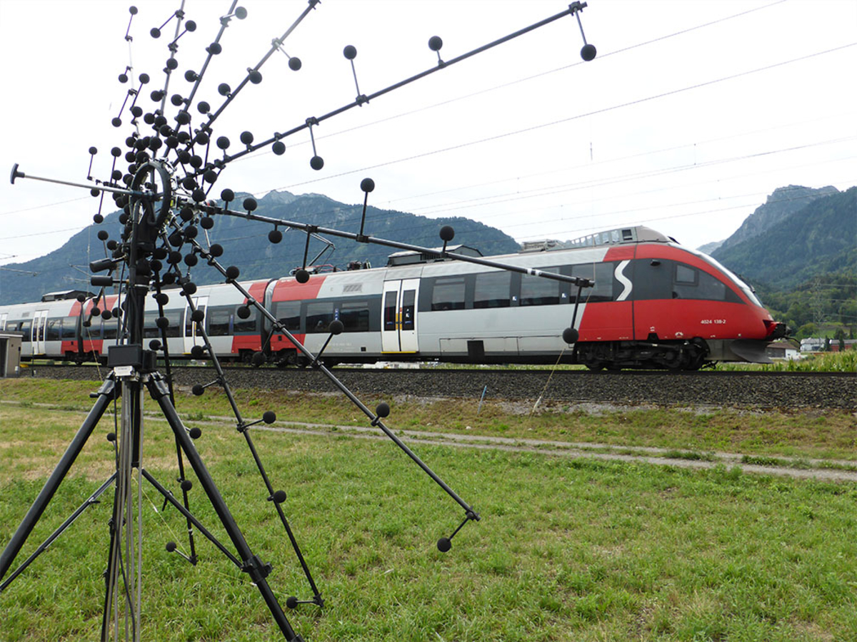
The delay-and-sum beamforming technique used in the PassBy module is widely used to analyze and localize sound sources, including those generated by fast-moving objects. When applied to fast-moving objects such as trains, the delay-and-sum beamforming algorithm adjusts the time delay and amplitude of the signals received by each microphone in the array. Dynamic sound sources can thus be effectively tracked and localized.

In the case of fast-moving objects such as a passing train, the sound signals picked up by the microphones exhibit frequency changes due to the Doppler effect. The Doppler effect occurs when the source of a sound signal passes a fixed position of the observer and the measurement tool, causing a change in the perceived frequency.

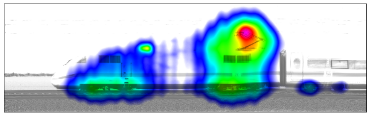
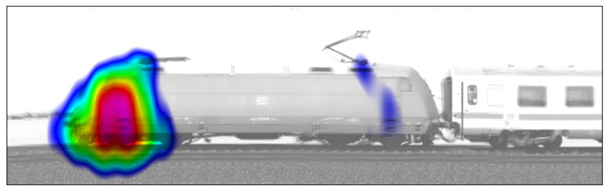
To account for this, the delay-and-sum beamforming algorithm takes into account the speed and direction of the moving object, such as a train, and adjusts the time delay and amplitude of the microphone signals accordingly. By taking into account the Doppler effect and compensating for the frequency shifts caused by the moving train, the algorithm can provide accurate measurements of the actual sound characteristics of the passing train.