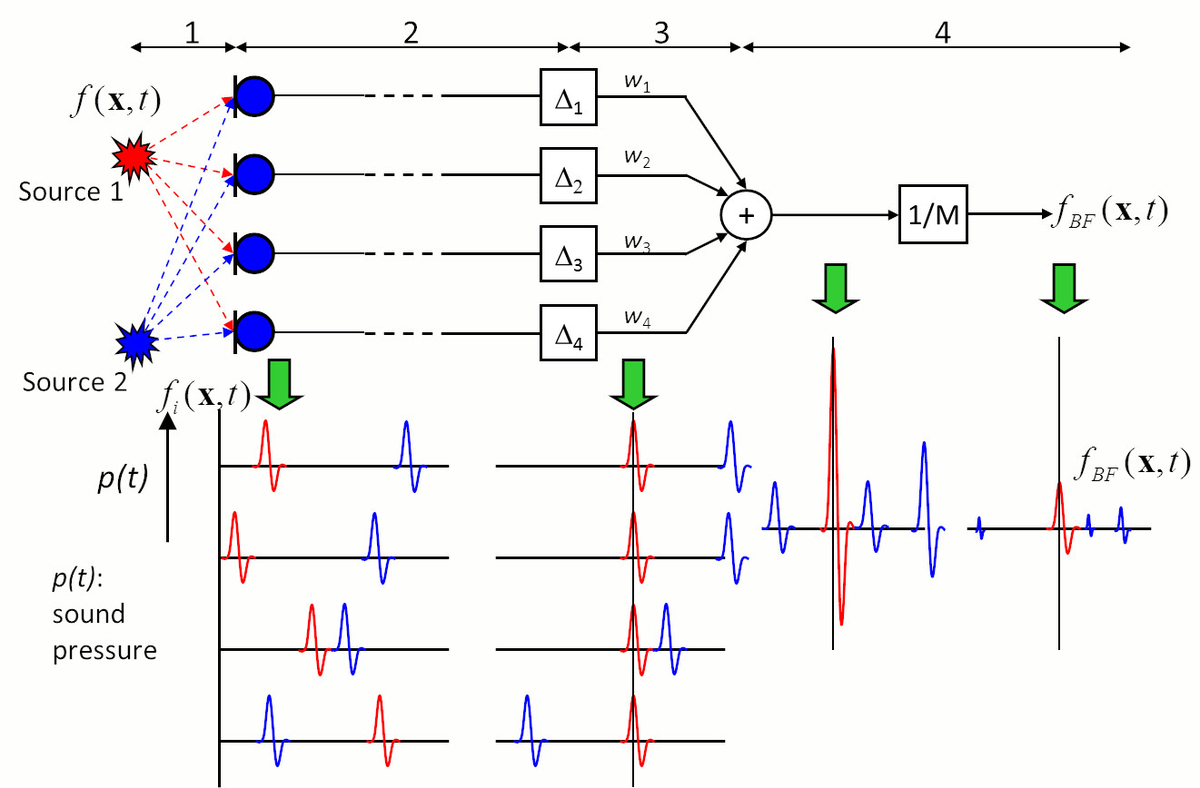
The rationale of the Delay-And-Sum Beamformer can be described by decomposing the signal processing into four main steps. The block diagram in Fig. 1 illustrates the case of two point sources situated in front of the microphone array.
- The sound of each source travels to every microphone along different paths.
- The signals captured by the microphones are similar in wave form, but show different delays and phases. Both are proportional to the travelled distances. The delays can be determined from the speed of sound, the distance between the microphones, and the sound sources. In Fig. 1, the Beamformer targets the point where source 1 is situated.
- The signal of each microphone is shifted by a corresponding runtime difference depending on the focus point. As a result, the signal components of Source 1 (red impulses) in all channels are in phase, whereas the signal components originating from Source 2 (blue impulses) are out of phase.
- The signals of all channels are added together and finally, the summed signal is normalised by the number of microphone channels. The result of this process \(f_{BF}(x,t)\) is illustrated above (see Fig. 1). The amplitude of the signal component of Source 1 (red) in the sum signal is as strong as the original amplitude of Source 1 and the signal components originating from Source 2 (blue) are negligible. The RMS or maximum value can be calculated from the time signal \(f_{BF}(x,t)\) and visualized in the acoustic map.