While Rotational Beamforming is a powerful method, several practical setup mistakes can significantly degrade the results’ quality. To avoid these issues, this FAQ describes approaches with regard to the most common mistakes.
Array plane misalignment
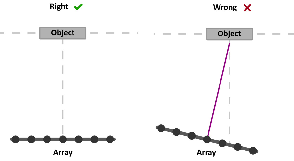
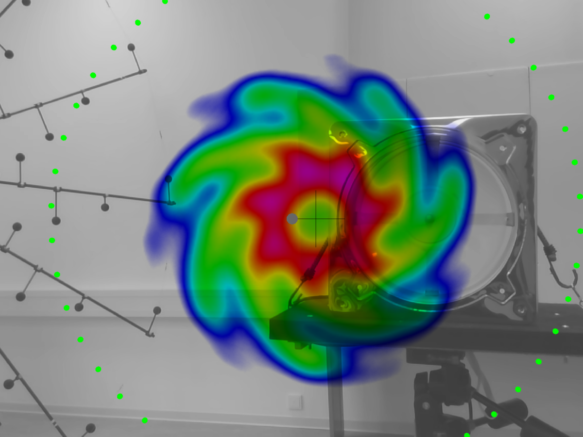
A key RBF requirement is proper alignment of the array relative to the object. The array must be placed parallel to the plane of the object of interest. Fig. 1 illustrates the correct and wrong way to align a microphone array with regard to an object, while Fig. 2 showcases the impact of misalignment on the beamforming result.
Array center misalignment
In addition to the plane misalignment, another common issue is the incorrect centering of the array relative to the rotating object.
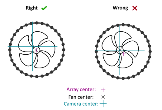
Important: the trihedral marker (large cross across the image) may look like the array’s center indicator, but in reality, it refers to the center of the optical image of the Acoustic Camera. NoiseImage provides a convenient method for centering: while in measurement preview mode, enable Show array in Photo 2D view, which indicates the array center with a small cross (noticeable in figures 2 and 4).
In the case where the array’s camera is mounted centrally (i.e.,Ring48 AC Pro), the center of the optical image and the center of the microphone array coincide in the display and are therefore indistinguishable. However, there are cases where the arrays camera is mounted eccentrically (like for the array Fibonacci 96 AC Pro) it becomes possible to distinguish them. Consequently, when a large cross is visible, it indicates the center of the optical image, and the center of the array is visible once the option Show arraywas toggled in the NoiseImage toolbar.
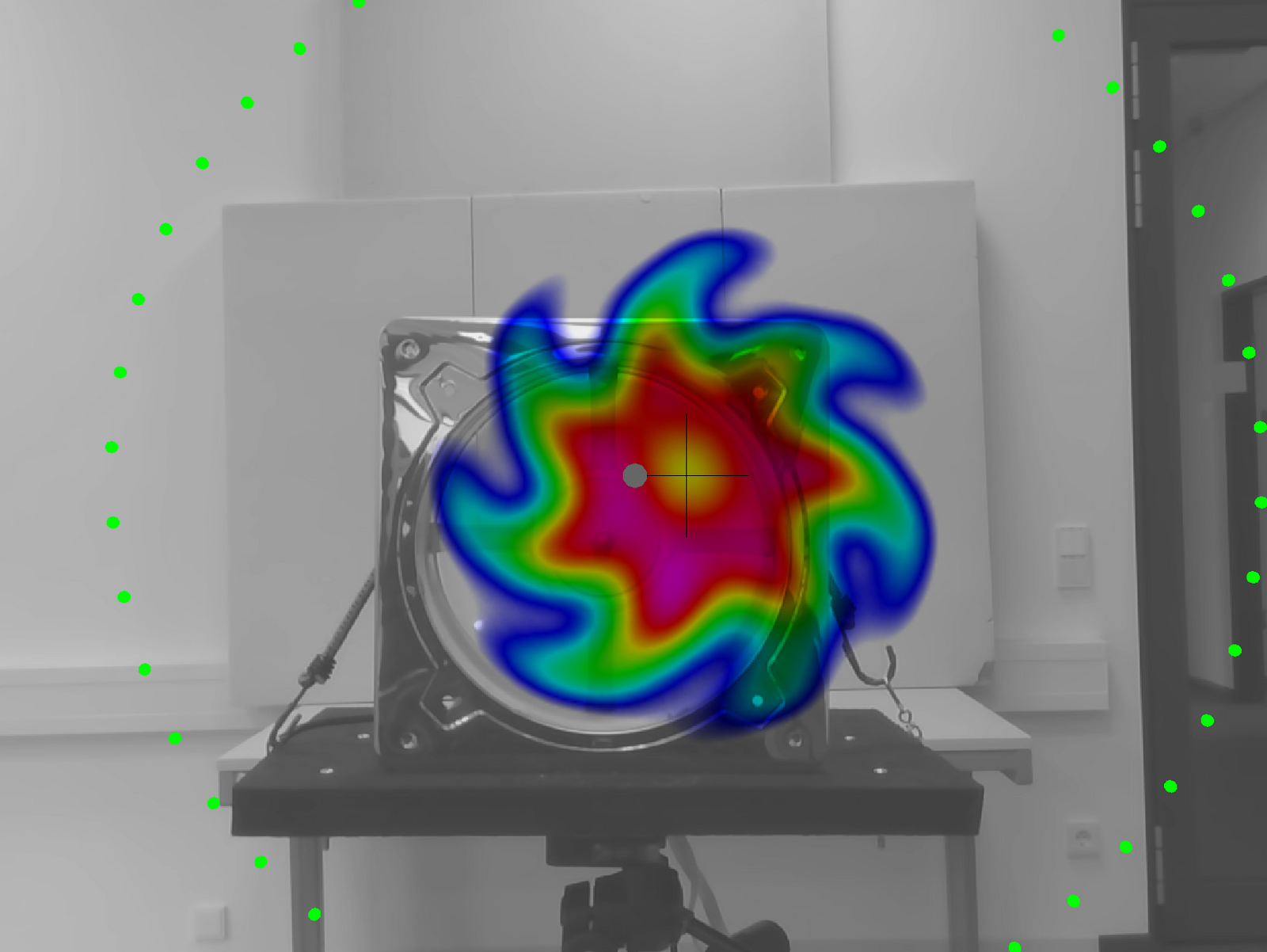
In conclusion, aligning the object to the optical center induces errors in the array virtual transformation (performed by the rotational filter algorithm). Fig. 3 illustrates the correct centering, while Fig. 4 displays the effect off-centering alignment.
Laser sensor associated errors
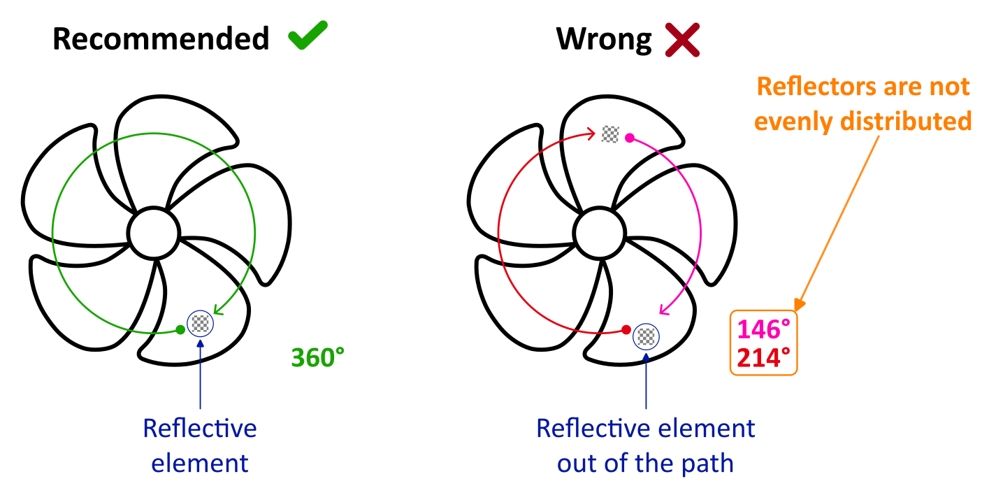
When the RPM signal cannot be acquired directly from the object, an external sensor, such as a laser sensor, can be used. In these cases, a reflective element is typically attached to a rotating part (e.g., a fan blade), in which each time that the element crosses the laser beam, a pulse is generated, allowing the system to calculate the rotational speed.
However, a frequent setup mistake made while using this reflective element involves using multiple elements under the assumption that this increases accuracy. In fact, it often reduces accuracy if the elements aren’t precisely distributed over 360°. Fig. 5 shows an example with two elements that are not exactly 180° apart, leading to inaccurate RPM data.
Best practice is to use only one reflective element, especially since most fans have an odd number of blades, making symmetrical distribution difficult.
Finally, highly reflective surfaces (e.g., metallic fan blades) can lead to false triggers and irregular RPM signals. To mitigate this, consider:
- applying a matte covering to the reflective areas;
- using spray paint to reduce surface reflectivity; or
- adjusting ambient lighting to prevent unintended reflections from triggering the sensor.